All stresses that occur in materials even without there being any external forces are called residual stresses. Residual stresses (internal stresses) exist in most manufactured parts and their potential to improve or ruin components.
They influence a mechanical component’s behavior as they:
- affect structural and dimensional stability
- reduce fatigue strength and crack resistance
- encourage surface crack growth.
Residual stresses can be originated by several causes (and their combination):
- Mechanical (based on plasticity deformations. E.g. Forging, shot peening)
- Thermal (based on cooling gradients. E.g. Heat treatments)
- Metallurgical (based on metallurgical variation. E.g. Welding)
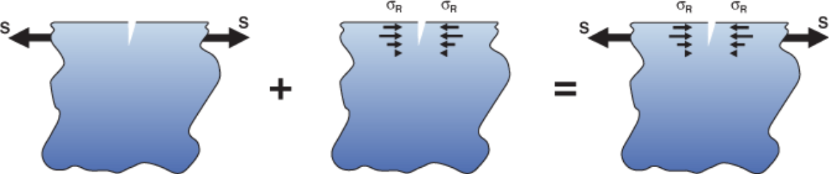
Residual stresses are self-balanced within the component: it means that, in absence of any external load, the composition of all the forces and all the moments acting of the workpiece are equal to zero.
Origin of residual stresses
The total stress experienced by the material at a given location within a component is equal to the residual stress plus the applied stress.
𝜎𝑇𝑂𝑇𝐴𝐿 = 𝜎𝑅𝑆 + 𝜎𝐸𝑋𝑇
Residual stress vs Applied Load
- Shot Peening (e.g. Residual stress)
- External Load (e.g. Bending)
- Total Applied Loads
Industries
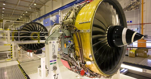
Aerospace industry (airplane and aerospace applications)
Automotive industry (series production, sport races and competitions)
Energy production (steam, wind and nuclear power plants)
Typical application fields of residual stress
The main strain gage methods used for measuring residual stresses are the following:
Strain gage methods for measuring residual stresses
Sectioning / Layer removal
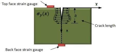
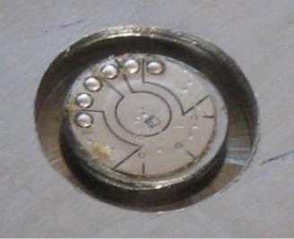
Hole drilling strain gage method
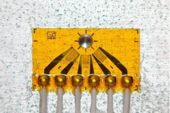
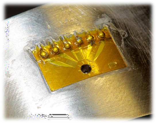
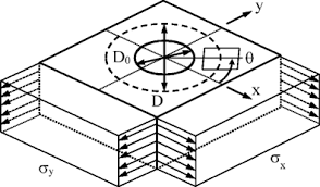
The hole drilling method consists in drilling a small hole (approx. 1.8 mm x 1.0 mm) into the center of a special 3-element strain rosette.
Textbox 79, TextboxThe MTS3000 system employs the high-speed drilling technique. It was introduced and studied by Flaman in 1982.
The high-speed drilling system comprises:
- a high-speed air turbine 400.000 RPM (at 4 bars of pressure)
- a tungsten carbide inverted cone milling cutter
The main operations involved in performing a residual stress measurement by the HOLE-
DRILLING METHOD are:
- Install a three-element strain gage rosette
- Center the drilling device with the center of the rosette
- Establish the initial contact between the workpiece and drilling device (zero setting)
- Drill a through hole or blind hole in depth steps up to the final depth (depending on the intended calculation method)
- Record strains released through residual stress relaxation by each grid of the rosette
- Measure the actual hole diameter
- Calculate residual stresses from recorded strains using the most appropriate method (ASTM E837-20 for uniform and non-uniform stress fields, ASTM E837-13 for uniform and non-uniform stress fields, ASTM E837-08, Integral method, Differential method, HDM method)
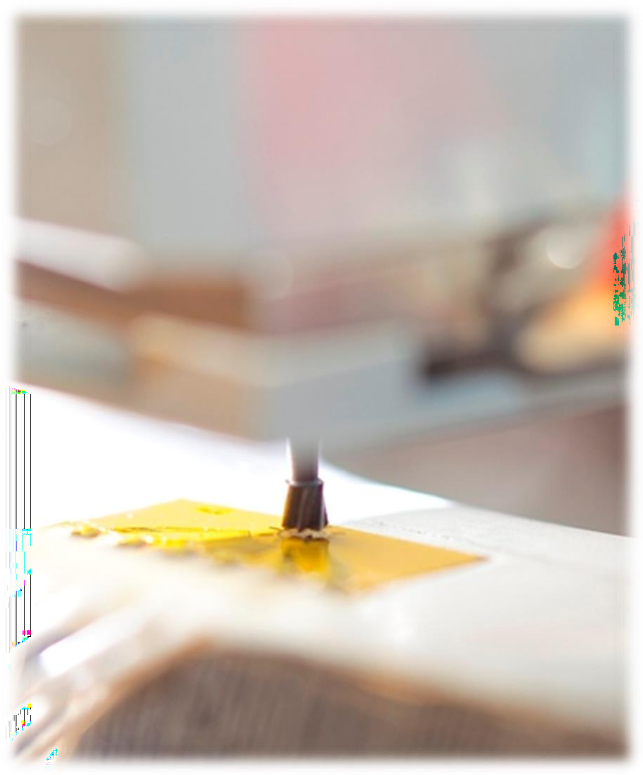
Hole drilling strain gage method: Zero setting
Hole drilling strain gage method: Drilling process
ASTM E837-20: Introduction
The hole-drilling strain-gage method is the only method for calculating residual stress that is STANDARDIZED at world level (ASTM E837).
The first version of this standard dates back to 1989, the latest version is available from November 2020.
Standard ASTM E837-20 specifies:
- Limit of applicability of the method
- The total drilling / analysis depth and the applicable calculation algorithms
- The number of drilling increments required
- The numerical coefficients for determining the value of residual stresses
- The data processing method and the measurement-related uncertainty
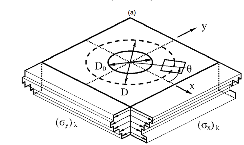
According to ASTM E837-20, a testing workpiece can be defined as following:
- Thin Workpiece: Workpiece whose thickness is sufficiently small that its strain versus hole depth response is proportional to its thickness.
- Thick Workpiece: Workpiece whose thickness is sufficiently large that its strain versus hole depth response is independent of its thickness.
- Intermediate Workpiece: Workpiece whose thickness is between that of thin and thick workpieces.
THIN WORKPIECE
- Thickness lower than 0.25 DGAGE
- Stresses are assumed to be uniform in the entire drilling depth
INTERMEDIATE WORKPIECE
- Thickness between 0.25 DGAGE and 0.6 DGAGE
- Stresses can be assumed to be uniform or non-uniform
THICK WORKPIECE
- Thickness higher than 0.6 DGAGE
- Stresses can be assumed to be uniform or non-uniform
ASTM E837-20: Workpiece definition
ASTM E837-20: Calculation cases
Definition of the calculation strategy of the standard ASTM E837-20:
UNIFORM STRESS FIELD CALCULATION
- Stresses are assumed to be uniform in the entire drilling depth
- Suitable for Thin, Intermediate, and Thick workpieces
- For Thick and Intermediate workpieces, this calculation is appropriate when prior information is available or for determining a representative magnitude of the residual stresses present
NOT UNIFORM STRESS FIELD CALCULATION
- Stresses are assumed to be non-uniform in the entire drilling depth
- Plot of residual stress up to the total calculation depth (principal stresses and principal angle)
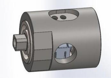
The MTS3000 – RESTAN system
The MTS3000 system is the only fully AUTOMATIC instrument in the world for determining residual stress by the hole-drilling method.
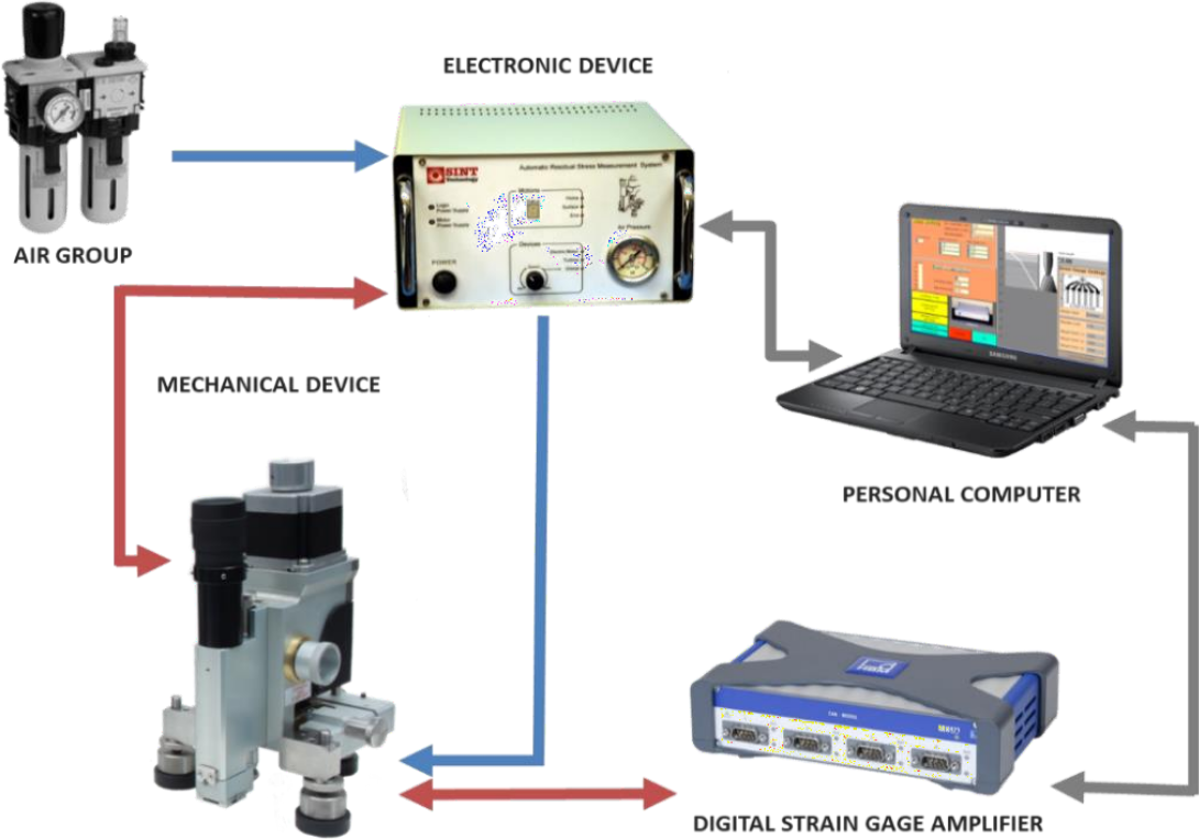
The MTS3000 system consists of:
- A mechanical setup housing the optical system and drilling system
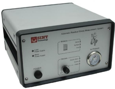
- An electronic control unit
- A digital strain gage amplifier (HBM Quantum X)
- Control (RSM) and back-calculation software (EVAL)
The chief advantages in using an AUTOMATIC system are:
- Higher repeatability and accuracy of measurement
- Higher hole drilling accuracy
- Shorter testing time
HIGHER PRODUCTIVITY REDUCTION IN COSTS
- Suitable for field or laboratory applications
- Evaluation of residual stresses as a function of depth
- Facility to accurately perform drilling steps up to 5 microns
- Choice of back-calculation methods
ANALYSIS METHODS
- ASTM E837 – Uniform
- ASTM E837 – Non-uniform
- Differential Method
- HDM Method
The MTS3000 – RESTAN system: fields of applications
The MTS3000 system can be used to determine residual stresses on a wide variety of materials, such as:
CHOICE OF CONFIGURATION
- Standard Metals (e.g., Steel, Aluminum, Cast Iron)
- Non-Standard Metals (e.g., Titanium, High Tensile Steels)
- Polymeric (e.g., ABS, Polycarbonate)
- Composites
CHOICE OF TYPE OF CUTTER
- Drilling Devices
- Air turbine drilling device
- Electric motor drilling device
- Orbital drilling device
- Parameters
- Feed rate (mm/min)
- Drilling speed (RPM)
- Delay time (s)
- Tool Materials
- Tungsten carbide (CT)
- Tungsten carbide with coating (CTT)
- Diamond (D)
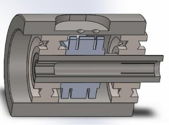
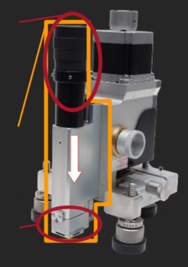
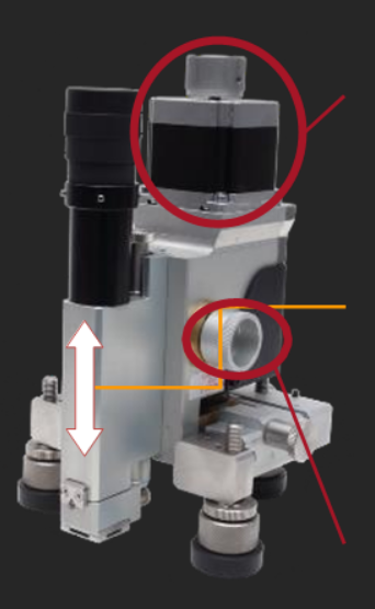
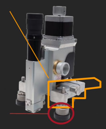
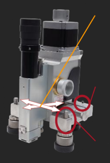
The MTS3000 – RESTAN system: mechanical setup
Accuracy in hole drilling with a centering system achieved by aligning a microscope with the turbine drilling target.
Automatic and manual vertical movement system. Automatic vertical feed uncertainty equal to ±0.005 mm.
Positioning on the x-y plane surface with micrometer screws and monitoring hole eccentricity by two centesimal dial gauges.
Positioning of the system in any operating condition with three adjustable-angle, wide-based magnetic feet.